|
With our whole VC10 model, detailed on a separate link, we
offer the only 3D Virtual Cockpit for this aircraft!
Every individual gauge was carefully photographed by David Chester and
their functions lovingly re-created with extreme accuracy. Everything is
true to life within the
confines of the simulation and computer screen and a little Artistic
Licence! David's natural talent for photography and
his skill as a programmer are magnificently combined here, for the first
time, to produce what we consider to be the finest and most realistic panel
available for the Vickers Super VC-10, one of the most incredible aircraft
ever made. We are absolutely certain that you will agree.
Our panel has been designed and developed with and tested by real pilots who have been involved with the making of this
panel right from the outset.
We reserve the right to change our simulation, panel, model, instruments and pricing without notice.
Customers will be able to download the latest version at no additional
charge.
Please note that all of these images are the property of David Chester and
Abacus Systems Ltd and must not be used without our consent.
If you want some
photos to make your own panel then either ask us first, or better still go
and pay Brooklands Museum £7 for an excellent day out and take some pictures
yourself! ;) We cannot recommend Brooklands enough. The whole team there are
friendly, helpful and knowledgeable and there are not may - if any - places
where you can actually sit at the controls of an aircraft and talk to
someone who was involved in its design, maintenance or sales.
We are showing these images in as much detail as possible so that you can
get an idea of what David has put into it. To get the full impact though you
will need to actually use the product at 1600 x 1200 or 1280 x 1024
resolution from within Flight Simulator! Please note that the minimum
resolution is 1024 x 768 with a recommended resolution of 1280x1024 and
1600x1200 on 17m 18 or 19 inch monitors! This is a Hi-Fidelity simulation
designed to run on fast modern computers. We are not catering for
low resolutions, although you may feel that FS2002/4 is acceptable at 800 x 600 we
do not and
we have not, therefore, included any low-res bitmaps. |
|
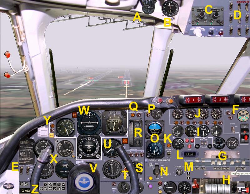
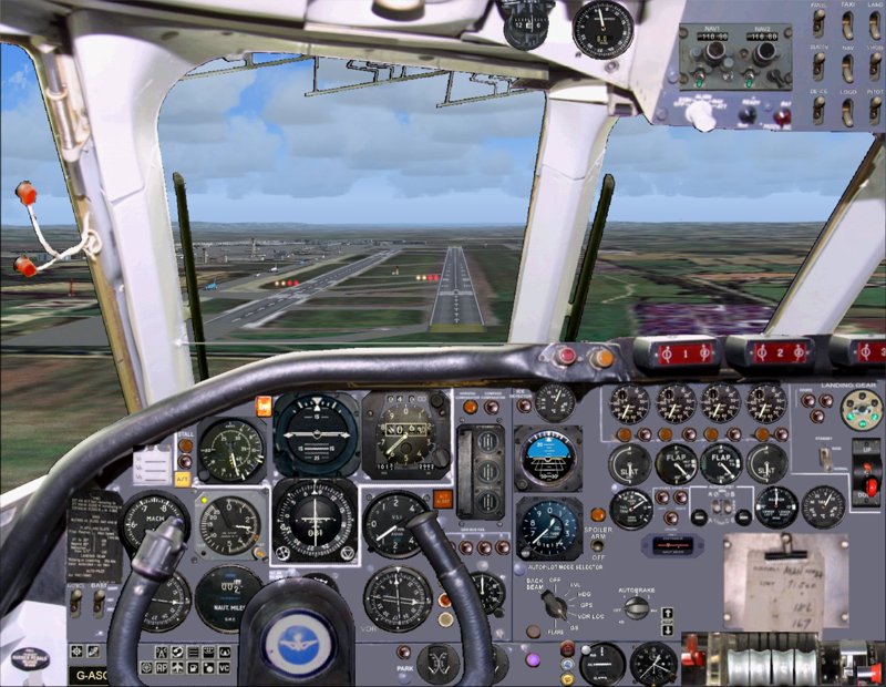
This is the main panel reduced to 800x600 resolution. It looks far better at 1280x1024 or
1600x1200 ! As does the more close-up IFR Panel shown elsewhere on this
page.
An explanation of the
instruments:
Firstly, I would like to explain that we have re-created the VC10 panel
with as much accuracy as possible within the limitations of Flight Simulator
and the confines of the computer screen. We have kept "Artistic Licence" to an absolute minimum
but some items have had to be changed slightly to provide
usability with Flight Simulator - particularly with the autopilot. We have
opted to use the selector mode knob on the main panel for ease of use. The
main switch bar from the centre console is on a pop-up selected by clicking
on the AP Sim Icon next to yoke. It appears just above the throttle
quadrant. In the full aircraft model's virtual cockpit these are on the centre
console where they belong, but the pop-up also works. We feel confident that you will not be disappointed. Where
possible we have detailed the differences from the real aircraft.
A - Whisky Compass. A basic no-frills magnetic compass for backup purposes.
B -
Wind Speed and Direction. This gauge was completely made up by David from
bits of other VC10 gauges.
C - NAV Radio with Ident. Settings for navigational beacons including ILS on
NAV1. The green Ident switch plays an audio Morse code 3 letter name of the
VOR beacon or ILS you are tuned to. The real Super-VC10 had 2 ADFs (basic
direction finders) up here instead. We have put those on the main Radio
Panel which is on the centre console as per the Standard VC10 at Brooklands
Museum. NAV1 is used for the ILS frequency and DME1 distance gauge. NAV2 is
used to activate the DME2 distance gauge.
D - Lighting switches, Pitot Heat and De-Ice. The Ice Detector light (P)
will illuminate when heating is required. Both Pitot Heat and De-Ice need to
be on to extinguish the warning light.
E - Avionics and Battery Master Switches. This is not the correct
location for these switches but they are placed here for convenience. The
real switch in this location has no function in Flight Simulator.
F - Landing Gear section. Here we find the gear position indicator. 3 green
lights means gear is down and locked. 3 red lights gear is in motion. The 3
red doors lights also illuminate when the gear doors are in transit. The large
red gear knob raises or lowers the landing gear by clicking on it.
G - Autopilot Main Switches. These pop up onto the main panel above
the throttles when you click on the AP Icon next to the yoke. A little "artistic licence" has had
to be used here.
The real autopilot bar is the other side of the throttles on the centre
console. After a lot of consideration came up with something that is pretty
accurate but also very useable and will be familiar to hardened
flight-simmers :) We have, therefore, changed some switches in order to
integrate
features of Microsoft Flight Simulator.
For example the real VC10 has 2 autopilots AP-1 and AP-2 and 2 yaw dampers.
We can only simulate one of each in FS2002/4 so we use AP-1 as the Master
on/off switch and the FD or Flight Director switch replaces the "NAV" switch
on the real aircraft. The early mode knob which we have chosen to simulate
is also accompanied by a
bigger knob under the main switch bar on the centre console. We have elected to go for "down
is off" to remain true to the rest of the aircraft controls. Note that there is no separate
auto-throttle master switch. Next to the bar is a purple
light which lights when the autopilot is on. This is to aid you, the virtual
pilot. The real light is red and lights when the autopilot is OFF (we do
also simulate this indicator correctly under the autobrake knob). This is
also true of the AutoThrottle (A/T) warning light over at the left side of
the screen. We show it lit when the autopilot controls the aircraft speed
whereas the real aircraft shows it lit when the autothrottle is "off".
(For your convenience we have also placed a secret switch over there in the
form of the speed reference tag next to the stall lights. The top line
engages the TOGA take off power function. This gives you 95% power and 8
degrees of nose up for takeoff or for aborted landings. The second line
engages the Autothrottle speed hold at 250 knots. Finally, clicking on the
bottom line engages the Autopilot Altitude hold for the pre-programmed
altitude. Note that for the autopilot to function you must have the Ap-1
master switch on which can also be achieved by pressing the Z key or
clicking on the purple light in the middle of the panel to the right of the
Mode Knob. )
On the switch bar, the Autopilot Master switch is labelled AP-1. FD or Flight Director
engages automatically when you set autopilot functions. DAMP engages the
Yaw Damper which in FS200x restricts rudder movement. ALT engages the
Altitude Hold which will take the aircraft to the programmed altitude at the
programmed rate.
ATT holds the current attitude. TOGA sets the engine power to
take-off/go-around (90-95% or so) and gives about 8 degrees of nose up. The IAS switch
turns on the Airspeed Hold and the MACH switch engages the programmed Mach number. The
settings for Air Speed, Mach, Altitude, Heading and Course are set using the
appropriate main gauges which are fitted with turnable knobs for this
purpose.
Underneath the switch bar is a line of number cylinders. These are secondary
setting dials for ease of use and are completely unrealistic to this
aircraft. We have, however, included them because flight simmers are used to
using them. We have made them "in style" with this age of aircraft. Clicking
on the left side lowers the numbers and the right side increases the
numbers. Where possible we recommend using the appropriate gauge instead to
maintain realism. For example there is a knob and a bug on the airspeed
indicator for setting the required speed, and a knob and numbers on the top
of the Altimeter for setting the required altitude. For the climb rate
though you will have to use the number cylinder under the ATT switch.
H - Throttle Quadrant, Flaps/Slats Levers and parking brake. From the left
is the parking brake lever. On the real aircraft this is actually a switch
for linking the speed brakes to the ailerons but we cannot simulate this in
FS2002/4 as they are permanently engaged. The real parking brake is close by but "off-screen"
next to the seat. We have not included a speed brake lever in the 2D cockpit
(although it is there in the full model's 3D Virtual Cockpit) but you can
extend or retract the speedbrakes by clicking on the speedbrake light to the
left of the flaps gauges. Underneath is also a switch for engaging the
autospoilers before landing. This was not a facility on the real VC10 but we
have included it as simmers are used to it. (See K below).
The throttles are moved by clicking at the top or bottom for full power or
cut power. Clicking near the top or bottom slowly increases or decreases
power. They Also move to reflect the throttle position as set by a game
controller throttle control which is the preferred method.
Finally on the right side are the Flaps and Slats levers. We have simulated
this on our own VC10 model by using the first 2 positions for Slats only and
then the Flaps are added for each additional position. There is no separate
slats switch for FS2002/4 but as one would never use flaps without slats in
real life this works extremely realistically. I am informed that a notch of
slats were used in the climb.
The positions are:
Position Slats Flaps
Up 0 0
1 50% 0
2 100% 0
3 100% 14.5 degrees
5 100% 20.0 degrees
6 100% 35.0 degrees
7 100% 45.0 degrees
If you are not using our VC-10 simulation then you will need to adjust the
flaps and slats settings in your AIRCRAFT.CFG file to reflect this more
realistic set-up :)
Incidentally... the Airspeed indicator gauge has 3 small pointers which
slide around the outside edge. In real life the pilot sets these to the
correct V1, VR and V2 speeds according to payload etc. In FS2002/4 we are
able to do this automatically for you but have used them to indicate stall speeds. Please see the airspeed indicator
explanation (under W below).
I. Position indicators for the Slats, Flaps, Tail Trim and Ailerons.
There is also a TOAT gauge or Total Air Temperature. This is effectively the aircraft skin temperature at the hottest spot - normally the
nose. When the temperature drops below freezing the ice warning indicator is
illuminated and you should switch on the de-icer and Pitot heater. The Flaps
gauge is clickable to change the Slats/Flaps position. Click on the top half
for up and the bottom half for down. The same goes for the Trim Indicator
gauge. You can also click and hold. We recommend, however that you use the
levers like a real pilot or better still a programable yoke or joystick :) There are also 3 lights here which
illuminate when fuel drops below 10% in each tank group. The real aircraft
uses these lights to show a failure of the false "feel" applied to the yoke.
We cannot simulate that and we felt that a fuel warning would be useful.
J. Engine speeds (N2) for engines 1 to 4. Under each engine is a yellow
"reverser on" light and a red failure light. When an engine fails this will
light up. You can also click it to simulate an engine failure, and click it
again to cure it. You will need to restart the engine from the engine panel
by raising the 2 switches for cock and pump and then hold the start lever
until the engine fires up (or just press control/E to autostart). RAF models were fitted with a triple cartridge
starting system not unlike a shotgun cartridge but I am told that these were
not allowed on civilian aircraft. Instead, power was obtained by deploying a
propeller driven generator under the starboard wing which provided enough
power to start an engine should a 4 engine failure occur in flight <shudder>.
K. Autospoilers. Not realistic for the VC-10. We utilised the VC10's INS switch for this (Inertial
Navigation System was fitted to some aircraft). Setting this on (up) will automatically raise the spoilers at
touchdown. They retract when you cancel the reverse thrusters by increasing
the throttle slightly. The Yellow light illuminates
when the spoilers (air brakes) are extended and you can also extend them manually
or in flight by clicking on the light itself. Many of our indicators and
gauges are
also clickable, like Autothrottle, Parking brake, Autopilot Off.
L. DME2. This shows the distance from the VOR beacon programmed in by the
frequency set on NAV2 when it is available. DME1 is over on the left side
and is a big round thing.
M. Auto-Brakes. Again not realistic to this genre of aircraft, but it allows
automatic use of the brakes for aborted take-offs and for landings. The AB
setting will cause the brakes to come on if you abort a take off and FS2002/4
detects that you have done so. In my own tests this seems to be a rare
occurrence!. The other settings 1, 2, 3 and Max are used
for landings. I would suggest using 2 or 3 normally. When The aircraft speed
drops below 20 knots the brakes are automatically turned off again. If you
have left the reversers on they will be cut then too although you are not
supposed to use reversers below 60 knots in case the engines suck up debris
blown up from
the runway. Applying a little throttle at 60 knots and cutting again will
cancel the reversers and autospoilers for you.
N. The Autopilot Mode selection knob. The real VC10 also has a larger
duplication of this knob under the main autopilot switch bar. The functions are basically the same although we have
added those of the second switch into our older switch for ease of use, plus added
a GPS
setting. VC-10s were a bit early for Global Positioning systems but used an
Inertial Navigation System which was engaged using a separate
switch. (We use this switch for our autospoilers!) We have opted for a GPS position
on our rotary switch to take advantage of the FS2002/4 GPS and. therefore, make life
easier for you! Also, having it on this knob makes it impossible to try to
engage the ILS system when you are in "GPS Mode" rather than "NAV Mode" - a
common annoying error of some flight simmers!
This switch basically controls the guidance systems side of the
autopilot. In the Off position the red "A/P off" light to its right will
illuminate to warn that the aircraft is being steered by the human pilots.
In the LVL position it will simply keep the wings level.
The HDG position will cause the aircraft to fly on the heading programmed in
using the heading bug on the HSI gauge (Horizontal Situation Indicator).
The GPS position will fly to the point programmed into the portable GPS that
your pilot has in his pocket :)
The NAV/LOC position flies towards the VOR or ILS beacon programmed into the NAV1
radio.
The GS position does the same as the NAV/LOC position with the addition of
locking onto the ILS Glide Slope for landing approach. The aircraft should
be on autopilot and flying to intercept the ILS from a position below the
glideslope and at a reasonable heading angle for this to work - like any other aircraft in FS2002/4. When in
this position the blue "GS Arm" light to the right will illuminate if an ILS
signal is present. The yellow "GS Eng" light illuminates when the Glide Slope
is locked in. If it goes out this means that you have lost the ILS lock.
Finally the Flare position. The Glide Slope will be bringing you down at
something around 700 feet per minute depending on the approach path for that
airport. This is far too fast to land, although it probably won't break your
aircraft. In the final approach when you are about to land, rather than
switching off the autopilot and landing manually, you can click on the Flare
position and the aircraft will raise the nose (flare) to land smoothly.
At least that is the aim :) It can be engaged at any time that
you have an active glideslope, effectively making this an AutoLand which was
fitted to this aircraft in later years. The little light next to it changes from Blue to
Yellow to Orange to Green to White as your approach progresses. At white you
are just off the tarmac and you should disengage autothrottle, cut your engines and prepare to
engage the thrust reversers. Be aware that the autopilot switches off
directional lock on touchdown so you should be ready to use your rudders.
The VC10 was used as the test bed for the category 3 AutoLand later fitted to the
Trident.
We are also considering a fully automated landing system for this aircraft
which will check that the gear is
down, flaps extended and the power is cut at the correct moment. Reversers
would be applied, and the heading lock released. The reversers would be cut when the
speed drops below 60 knots. It would also check that the AutoBrakes and
Autospoilers were set for the fully automated lazy approach effect. This
will be available as a free upgrade to our customers when available.
O. The Standby Altimeter and Standby Artificial Horizon. These are here to
simulate those backup devices on the real aircraft. As well as this, the
standby Altimeter is fitted with a "QFE Switch". In real life approach
control will give you a number to dial in to calibrate the gauge to show
real height from the runway rather than the normal height above sea-level
according to barometric pressure. We cannot simulate this exactly currently
in FS2002/4 so we are using the radio height instead. This shows actual height from the
ground when the button is depressed. Click it to switch between normal and QFE mode.
The needles show the Hundreds and Thousands of feet and the moving white
semicircle shows the Tens of Thousands.
P. Outside Air Temperature in Celsius. Next to this gauge is a red light
which illuminates when the temperature drops to a certain level or when the
skin temperature (T.O.A.T) drops below freezing. This is a warning that you
need to switch on both the Pitot Heater and the De-Icer which you will find
on the upper panel. Switching both of these on will extinguish the warning
light.
Q. Artificial Horizon and Compass (HSI) failure warning lights.
R. Yaw Damper gauge. Although we are, sadly, not able to simulate this gauge
accurately in FS, we have used this to show main rudder and rudder trim
positions in order to bring it alive.
S. Timer. This is a minutes and seconds timer. Click the button to
start/stop/reset. On the Clock which is below and to the right the second
button (the one on the right) is used to increase and decrease simulation
rate.
Surface indicator. This shows the position of the main control surfaces;
Rudder, Ailerons and Elevators.
Generator Bus Fail. These light
up when the generators of the appropriate engine are not generating
electricity - eg when the engines are off.
T. OMI lights. These light up when you cross the Outer (O), Middle (M) and
Inner (I) marker beacons on landing approach. In FS2004 you will also get
Morse sounds which sadly do not work in 2002 due to a "feature" of that version
beyond our control :(
U. Vertical Speed Indicator or VSI. This shows the change in altitude
in feet per second. The normal climb-out rate for a VC-10 is 2300 feet per
minute. If you are not using our VC-10 simulation then you may want to change this setting in the [AUTOPILOT] section of your AIRCRAFT.CFG file. The default is 1500 feet per minute.
You will find, however, that the aircraft has a job maintaining 2300 fpm
when above 27000 feet. We recommend reducing to 1500 at or before that
point.
V. Here we have the Turn Coordinator gauge which shows slip and yaw. During
a turn you should try to keep the little white ball on the white line using
the rudders.
Under this and slightly right are the brake pressure gauges for main and parking brakes, left
and right main gear brakes. There is also a red warning light which is lit
when the parking brake is on. Clicking the light toggles the brakes on/off
just like the lever on the left of the throttle quadrant.
W. The main business section of the panel!
1. On the left the Airspeed Indicator shows the current indicated airspeed.
On the outer dial up to 200 knots and then the outer needle stays behind
while the inner needle shows airspeed up to about 430 knots. There is also a
yellow and black "barber pole" to show the maximum safe airspeed for the
current altitude. The autopilot airspeed setting is changed using the knob
at the bottom left corner of this gauge. A small triangular bug wizzes
around the gauge edge to show the current speed setting which is also
repeated numerically under the main autopilot switches on the right side of
the main panel. Also on this gauge - and uniquely I believe in flight
simulator - we have 3 little pointers just like the real aircraft to show
minimum speeds etc. Unlike the real thing though we are able to calculate
for you the minimum stall speeds with full flaps, No flaps and a yellow
moving pointer which shows the current stall speed for the current flaps
setting and fuel load! Enjoy!
2. The AutoThrottle warning light. Opposite to the Real Thing, our light
illuminates when the autothrottle is on and extinguishes when the
autothrottle (be it airspeed or Mach) is off. This is to keep in line with
other aircraft simulations so as not to cause confusion.
3. Artificial Horizon shows the attitude of the aircraft. The white line
follows the horizon and the line with the circle represents the aircraft. It
is also marked with 15 and 25 degrees nose up and down. The pointer at the
top shows the bank angle.
4. The Horizontal Situation Indicator or HSI (Giro compass with ILS
direction and glideslope needles), Course (for NAV1) and Heading bugs. This
is your main compass and shows your direction of flight with your current
heading shown at the top. Around the edge is the compass rose with 2 bugs
showing the autopilot Heading and Course setting.
The Course is shown by a solid white arrow and is controlled by the knob at
the bottom left. It is also shown numerically in the centre of the gauge and
also under the main autopilot switch bar.
The Heading is shown by an open triangle and is controlled using the knob at
the bottom right of the gauge displaying a similar open triangle. Clicking
to the left of the knob reduces the compass heading and to the right
increases it. The heading is also shown numerically for your convenience
just under the main autopilot switch bar.
5 The main Altimeter shows the current height above sea level. At the bottom
is the calibration setting for current barometer readings in Milibars and
inches of Mercury. This is altered by the knob at the bottom right corner of
the gauge. At the top of the gauge is the current autopilot height setting.
This is changed using the knob at the top right corner of the gauge in
hundreds of feet. The
numbers are also repeated for your convenience under the main autopilot
switch bar under the ALT switch.
X. This section comprises 4 gauges.
1. The Mach Indicator which has a knob on the bottom left for altering the
Mach Hold autopilot speed and is indicated by the moving triangle bug.
2. The Radio Altimeter measures the distance from the ground by radar. It
has a warning light in the top left corner and the decision height bug which
is controlled by the knob in the bottom right corner. This sets the height
at which the large Decision Height or DH light illuminates and is the "point
of no return" for landing.
3. Next is the DME or Distance Measuring Equipment. This shows a digital
readout of the distance from NAV1 if the beacon that the NAV1 radio is tuned
in to is fitted with distance measuring equipment. Normally this shows the
distance to the runway when your ILS is online. Please also see DME2 which
shows the distance to the VOR beacon that the NAV2 radio is tuned to. This
is especially useful when the ILS does not have distance measuring equipment
but the airport has a separate VOR beacon which does.
4. The Automatic Direction Finder or ADF is an old fashioned device that points to a Non Directional Beacon or
"NDB". It is not as smart as a VOR and is tuned using the ADF Radio on the
radio panel. It is, however, still quite useful for navigation generally.
Often this gauge was replaced with another VOR gauge on the real aircraft
and was invariably equipped with garish red and green needles!
Y. Stall warning and Decision Height lights. The Amber stall light
illuminates when a stall is imminent. The Red indicator lights up when a
stall is occurring. The DH light is programmed from the Radio Altimeter (see
X) and lights up when you go below the Decision Height. This is the height
below which you are committed to land. It is a larger version of the small
light on the Radio Altimeter (RADALT) gauge.
Z. This is the metal plaque which displays the aircraft's registration
letters.
Note also the location of the Icons
at the lower left for (from the left) Map, GPS and Radios display. ATC,
Kneeboard, overhead panel, Yoke on/off and (second row) Refueller Hoses
Deploy (For K3 model), AP-Autopilot switch
bar, Engineers panels for
Engines and Fuel, IFV/VFR panel switch and finally the VC switch turns off
display of a Virtual Cockpit in the 2D side views. We fitted this last
switch recently as turning off a virtual cockpit in this way stops the
landing and taxi lights from displaying in the forward view. It does not
effect the Virtual Cockpit itself in any way. In FS2004 our 3D Virtual
Cockpit is really all you need to fly this aircraft though. You can click on the instruments just as you can in the 2D cockpit.
Sadly this is not possible in FS2002 where you will need to return to the 2D
cockpit in order to click on the instruments.
* We reserve the right to change and update our simulation without
notice.
|
)
)
)
)
)
)
)
)